What can a CAN bus IMU do to make an autonomous vehicle safer?
CAN (Controller Area Network) is a robust and mature vehicle bus standard that allows devices to communicate with each other. Now over thirty years old, CAN is used on virtually all passenger vehicles as well as heavy equipment. A low-cost physical layer combined with robust and reliable transport layer delivers messages across the bus. As autonomous vehicles require many sensors to reliably exchange data, CAN is an excellent interface choice for a variety of low and medium speed vehicle sensors such as the Wheel Speed Sensor, Steering Angle Sensor, Throttle Position Sensor, and the Inertial Measurement Unit.
CAN Bus Network Diagram (Image Credit: Tek Eye)
Inertial Measurement Units (IMU’s) consist of three axes of acceleration plus three axes of angular rate measurements that are the linear and rotational components of a vehicle respectively. Not to be confused with single chip accel/gyro integrated circuit solutions, a temperature compensated and calibrated IMU module will deliver nearly zero bias drift over temperature and operating conditions. An IMU may also include three axis of magnetic field measurement used for electronic compass functionality.
While the CAN bus standard is pretty mature, only recently has CAN been frequently used to share IMU data with various subsystems on the vehicle. One example of a CAN-enabled IMU is ACEINNA’s OpenIMU300RI.
OpenIMU300RI CAN Bus IMU with Open Source Communication and Navigation Stack
The OpenIMU300RI is a 9-axis MEMS-based IMU that includes a CAN-interface, a RS-232 interface, and an ARM Coretex M4 CPU. The OpenIMU CPU can run both standard and custom algorithms created using ACEINNA’s free, open-source developer tool-chain.
So Why Create a Custom IMU App with CAN Bus?
In an autonomous vehicle CAN is used to pass IMU data to other sensors as well as the main vehicle control i.e., the vehicle’s brain. Some of our customers report using CAN bus to share IMU data with up to 20 other vehicle subsystems in parallel. This can include for example, LIDAR, Camera, Radar as well as primary compute engines all benefitting from one centrally mounted high-performance IMU on the vehicle.
A CAN bus based OpenIMU300RI application can also listen to other messages on the bus. This is a quite powerful feature. For example, the Dynamic Tilt algorithm supplied by ACEINNA with the VG_AHRS application could be performance enhanced by listening to messages such as Odometer or Vehicle Speed to better compensate for the influence of linear acceleration on dynamic roll and pitch. Also keep in mind the OpenIMU300RI has a RS-232 port which can be used to input or output additional data. For example, in ACEINNA’s INS navigation application, GPS Sensor data inputted via the OpenIMU300RI RS-232 channel is then fused with the OpenIMU300RI’s internal IMU for full GPS/INS sensor fusion.
The OpenIMU300RI supports both CAN 2.0A and CAN 2.0B messaging. This post will discuss two “out of the box” example applications and how to develop custom applications — the first using CAN2.0A and the second using CAN2.0B with J1939.
The CAN specification has two standards for messages: CAN 2.0A with an 11-bit message identifier, and an alternative standard CAN 2.0B with a 29-bit message identifier.
CAN2.0A vs CAN2.0B Message (Image Credit: Sparkfun Electronics)
Both message types have a maximum data payload of only 8 bytes. Standard CAN data rates are 250 kb/s, 500 kb/s, and 1Mb/s. In ACEINNA’s experience, both messages types, as well as all three-baud rates, are pretty common in the field. Consumer automobiles often use custom defined messages with 11-bit identifiers, whereas heavy equipment vehicles more commonly use the 29-bit identifiers and define messages according to the J1939 standard. Recently some applications are starting to use a newer CAN FD (“Flexible Data-Rate”) protocol that supports data payloads up to 64 bytes.
Due to the popularity of the CAN bus on vehicles, a CAN interface is a convenient and reliable way to pass IMU data to one or more subsystems on the vehicle.
How to Debug an Application Using CAN?
Inertial and GNSS navigation system developers may not be familiar with CAN bus; however, a CAN analyzer makes it is easy to get started and analyze CAN messages. Some typical analyzers include the PyCAN for Raspberry Pi3 (<$50), the Komodo CAN Solo (<$500) Analyzer, and Vector tools (>$1K)
A low-cost and flexible way to analyze CAN messages is to use the PyCAN Raspberry Pi3 shield. PyCAN adds CAN bus hardware to the classic Pi3 and there are Python and C language drivers available to write applications on the Pi3 with PyCAN. ACEINNA provides an open-source Python test applicationthat allows a user to read and parse messages from an OpenIMU300RI over CAN with the PyCAN.
A second way to get started is with a low-cost USB-based CAN analyzer. One example is the Komodo CAN Solo. This affordable device ships along with a standard Window’s PC GUI that captures and logs bus messages. This device requires no programming to use.
Finally, Vector makes a broad range of sophisticated CAN tools and software. Vector tools are heavily used in the automotive industry and support a very complete set of features. With Vector’s software tools it is easy to create and load “DBC” files and then log data in Engineering units as opposed to raw data. A DBC file is a plain-text file format that describes a set of CAN bus messages. Vector also supports industry standard message formats such as J1939. The only drawback of Vector’s hardware and software tools are their premium price tags.
A Simple CAN-based IMU using Custom Messages
Many automobiles use CAN2.0A messages (11-bit identifiers) for transmitting sensor data onto a CAN bus. These messages are often available over the OBDII port, but the message encoding is not globally standardized. The open source project opendbc seeks to “democratize access to the decoder ring of your car”. This opendbc project has cataloged a number of popular car’s message structure and published the corresponding DBC files on GitHub.
Here is an example of the Engine Data message from a 2017 Honda Odyssey:
Example CAN2.0A Message of Honda Odyssey
The first line “344” is the 11-bit message ID, and the corresponding lines describe how the 64-bit data payload is packed to encode transmission speed(s), engine rpm, odometer, counter, and checksum. Some key details of the DBC file format are defined on this handy GitHub page.
Similarly an IMU may define a set of messages for its accelerations, rates, and other IMU data. A DBC file is then created to describe the chosen encoding. Since a typical IMU sensor has 16-bits or more of resolution. All six or more axes of IMU data cannot fit into a single 8-byte CAN message data payload. So as the example below shows, the 3-acceleration values are encoded into one message and the 3-angular rate values are encoded into another message. In addition, a time stamp is added to both messages for time synchronization.
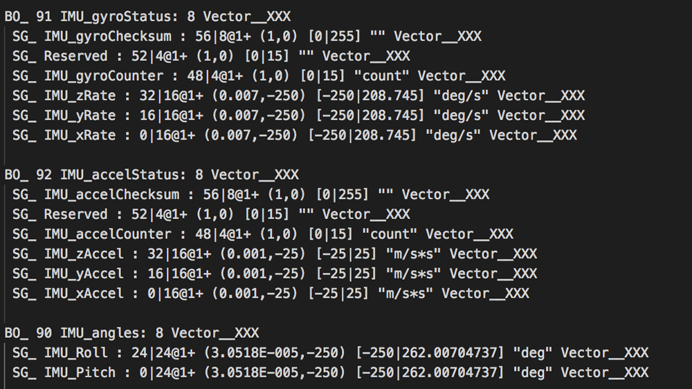
Sample CAN2.0A Message defined by OpenIMU300RI
Example OpenIMU300RI source code that outputs these messages is available. To use this source code, first install the ACEINNA extension for Microsoft Visual Studio code as described here, then compile and install this application.
J1939 based IMU and Dynamic Tilt Sensor
J1939 is a SAE standard for encoding vehicle sensor and diagnostic data using CAN 2.0B (29-bit Identifier) messages. J1939 makes sharing data much easier because the contents and scaling of the message’s data contents are globally standardized. J1939 also includes room for a device to have custom messages too.
A message in J1939 is called a Parameter Group Name or PGN and the PGN is part of the 29-bit identifier. For example, the PGN for Acceleration data is 61485. The data internal to the 61485 message is also standardized, and the individual x-axis, y-axis, and z-axis sensor readings are encoded with a “SLOT” number. SLOT is an acronym for Scaling, Limit, Offset and Transfer function. In J1939, the SLOT defines the individual sensor data encoding. For example, the Acceleration message has a SLOT Identifier of 303. The 303 SLOT encodes acceleration at 0.01 m/s² in the range of -320 to 320 m/s² with an offset of -320 m/s².
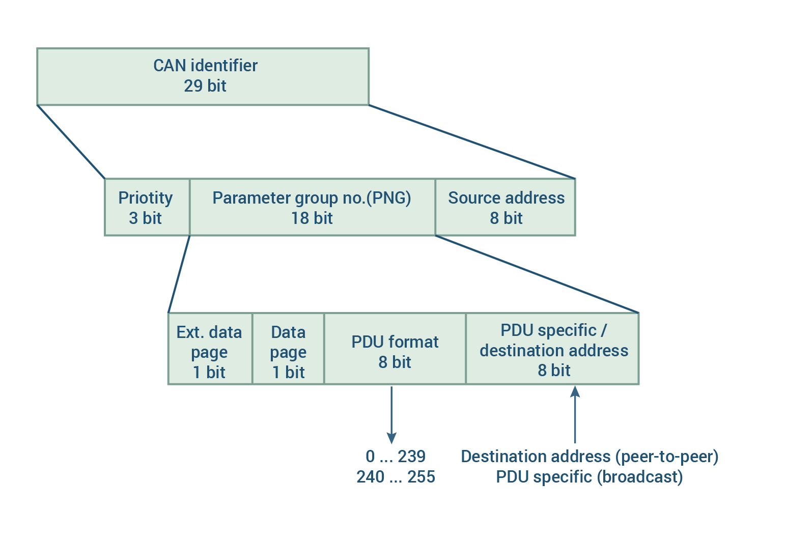
J1939 Message ID Definition (Image Credit: Ixxat)
ACEINNA’s official IMU application for OpenIMU300RI provides IMU output according to J1939 and the PGNs 61485 and 61482 for acceleration and rate respectively.
ACEINNA also supports a Dynamic Tilt algorithm for the OpenIMU300RI. ACEINNA refers to this algorithm as a “Vertical Gyro” and it is installed by compiling the VG_AHRS OpenIMU application for the OpenIMU300RI platform. Instructions are available on ACEINNA’s OpenIMU “read the docs website”. This algorithm computes the dynamic inclination i.e., roll and pitch by integrating the angular rate sensors to angle and then using the acceleration channels to establish a stable absolute reference with respect to gravity as well as correct for the long-term drift of the integration process. Here is a full blog post and video on the dynamic tilt algorithm. The J1939 Slope Sensor 2 Information message (PGN 61481) is used to encode dynamic roll and pitch.
J1939 is an internationally accepted standard. However, for convenience the message structure of a device such as an IMU using J1939 can still be documented with a DBC file. The linked DBC file shows how various messages — Acceleration, Angular Rate, and Slope Sensor 2 Information are encoded.
Writing You Own App
Now that we have the basics of CAN and OpenIMU300RI covered, let’s discuss how to write a custom IMU application using the OpenIMU300RI. First make sure ACEINNA’s tool chain is available by downloading Microsoft Visual Studio Code and then installing the ACEINNA extension. ACEINNA’s tool chain is available via VS Code on MAC, PC, and Ubuntu platforms. The best way to start a new OpenIMU300RI application is to use either of the example applications described above.
The diagram below shows the top-level data flow of an OpenIMU300RI application.
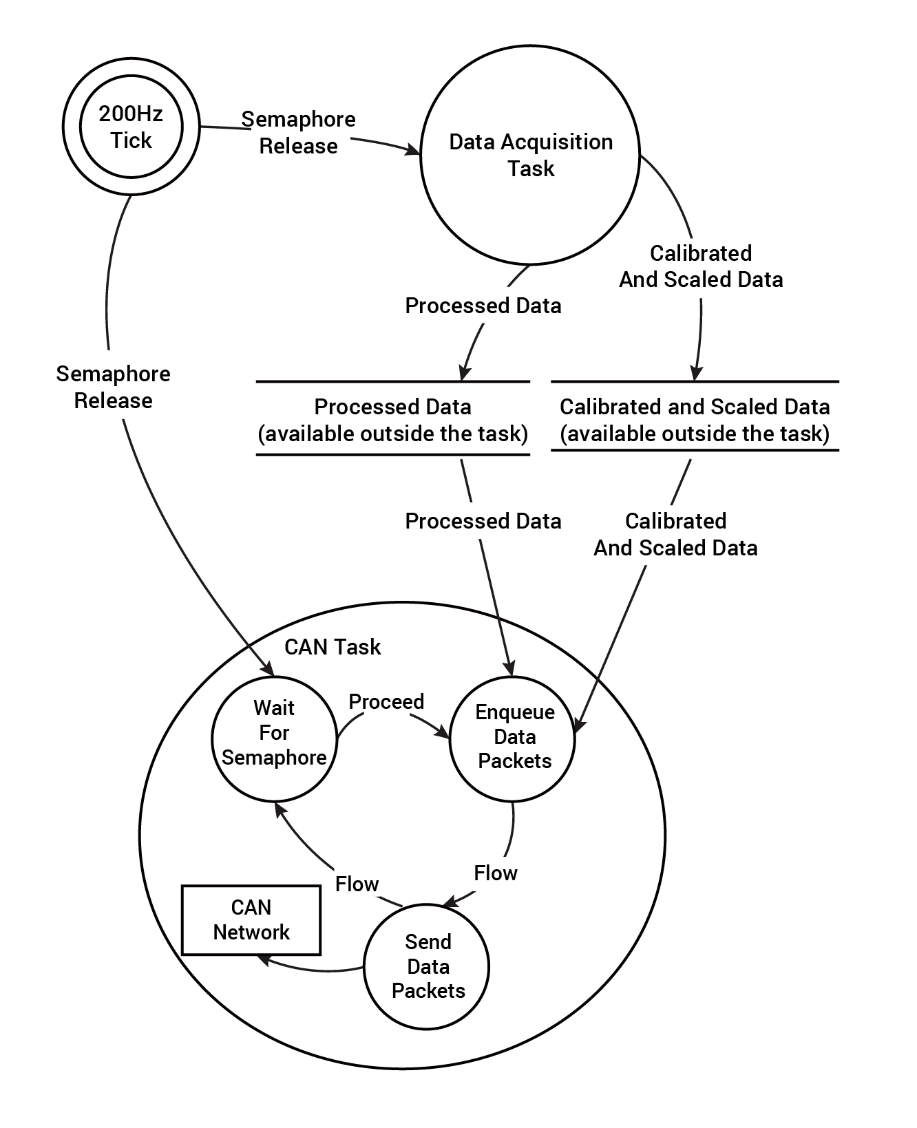
Block Flow Diagram of OpenIMU300RI Software
In summary, CAN is a popular standard bus that is extensively used in the vehicle industry. CAN is an excellent choice for IMU based navigation and control in autonomous or driver assist applications. The OpenIMU300RI’s open-source code and tool chain makes this integration process both straightforward and flexible.
AUTHOR BIO
Mike Horton is the CTO of ACEINNA where he is responsible for corporate technology strategy and inertial-navigation related technology development. Prior to ACEINNA, Mike Horton founded Crossbow Technology, a leader in MEMS-based inertial navigation systems and wireless sensor networks, with his advisor the late Dr. Richard Newton while at UC Berkeley. Crossbow Technology grew to $23M in revenue prior to being sold in two transactions (Moog, Inc and MEMSIC) totaling $50M. In addition to his role at ACEINNA, Mike is active as an angel investor with two Silicon Valley based angel groups - Band of Angels and Sand Hill Angels. He also actively mentors young entrepreneurs in the UC Berkeley research community. Mike has over 15 patents, and holds a BSEE and MSEE from UC Berkeley.
ABOUT ACEINNA
FOR MORE INFORMATION
Tel: 978-965-3200 Fax: 978-965-3201
Email: info@aceinna.com
Copyright©️2026. Aceinna All Rights Reserved.