IMU-based navigation will enable AV adoption
The global future of autonomous systems is based upon several strategic technological advances that will enable higher rates of autonomy.
The most significant advancement required is in the real time, constant, and accurate positioning of the vehicle throughout any environmental changes. Ubiquitous and safe autonomous vehicles, drones, and robotic systems alike must be able to achieve constant, consistent, and accurate sensing of their position in all weather, temperature, landscape environments, and dead reckoning for potentially longer periods of time than originally thought.
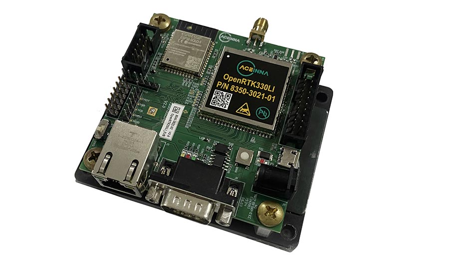
One of the most critical sensors in all positioning systems is the inertial measurement unit (IMU) which strives to understand the fundamental physics of motion. This fundamental understanding of how a vehicle is moving in time and space is useful for many applications and continues to be one of the most cost effective and accurate sensors fused to the vision and other detection and ranging systems.
Why are IMUs so important? Imagine a line drawn down the middle of a page which would constitute the perfect path an autonomous vehicle needs to travel in a tunnel. Let’s say it takes one hour from one end to reach the other end of this perfectly straight tunnel. If the dead reckoning solution of the vehicle has a bias instability of 3 degrees per hour, by the end of the tunnel the vehicle will be 3 degrees away from the line, at a given time interval, likely resulting in your vehicle hitting another vehicle, a wall, or both.
Currently, the performance of many IMUs in the market is still not accurate enough and requires a significant step-function improvement in sensor performance, specifically when the vehicle is operating under a dead reckoning situation for seconds or potentially minutes at a time.
There are two specifications that are important to understand when considering the overall performance of an IMU: bias instability and angle random walk (ARW).
Similar to an aircraft, ground vehicles are subject to motion about the lateral axis (pitch or incline/decline), roll (rarely a good motion to undertake), and yaw (turning orientation)—arguably the most important axis for autonomous systems—all of which contribute to the vehicle's current position and future position. Within the IMU, a MEMS (micro-electromechanical system)-based gyroscope, which measures angular rate, has several internal contributors to error, with bias instability as one component worth continuous improvement.
An IMU with six degrees-of-freedom is composed of multiple inertial MEMS sensors that are temperature compensated and calibrated to align on orthogonal axes. An internal three-axis gyroscope capability measures rotation about a known point while a three-axis accelerometer measures displacement.
Gyroscopes are subject to bias instabilities in which the initial absolute zero readings of the gyroscope will cause drift over time due to integration of inherent imperfections of the sensor and noise within the device.
Bias repeatability can be calibrated across known temperature ranges of the IMU, however integrating and injecting constant bias instability will cause angular error, which accumulate as the system estimates drift over the longer periods. The result of drift is that the error of a computed heading continuously increases, and consequently, the true position of the system continues to erode causing significant challenges to navigation and overall system accuracy.
The gyroscope drift is mainly due to the integration of two components: a slow-changing, near-DC variable called bias instability and a higher frequency noise variable or ARW measured over time.
The yaw axis is most sensitive to this drift while a portion of the pitch (attitude) and roll axis gyroscope drift can be removed within an IMU using accelerometer feedback to monitor position relative to gravity and other errors. Filtering the gyroscope output within an IMU using Kalman filters is a widely used method to cancel portions of drift error. This drift error remains a constant issue within the industry, and it is driving manufacturers to improve the sensitivity and overall performance of gyros for autonomous systems toward sub 0.05°/h bias instability specifications.
Thus, as we progress toward fully autonomous driving, higher levels of autonomous applications and freedoms will be enabled by the performance of more accurate and highly stable IMUs, specifically on the Z-axis or yaw gyro performance. As the yaw gyro performance is increased, we will see consumer vehicles, last-mile delivery robotics, and robo-taxi manufacturers make small incremental applications available along the way.
For instance, the summon and reverse summon features are examples of manufacturers leveraging parking and pick-up features of autonomous driving, which requires the combination of a dense real-time kinematic correction capability for position using satellite navigation to enhance the precision of positioning data derived from global navigation satellite systems (GNSS)—such as GPS, GLONASS, Galileo, NavIC, and Beidou—which provide accuracy to centimeter levels.
This capability, coupled with advanced camera systems for vision and high-performance IMUs for dead reckoning and physical measurements, is growing in popularity and increasing the demand for higher performance gyroscopes and sensors.
As we continue our pursuit toward fully autonomous systems—and with the recent issues surrounding COVID-19 highlighting the need for contactless delivery—the importance of effective and uninterrupted supply chains, autonomous delivery, robo-taxis, and fully autonomous driving will advance ever more rapidly, as will the requirement for increased performance of inertial measurement units coupled to vision-based systems.
ABOUT ACEINNA
FOR MORE INFORMATION
Tel: 978-965-3200 Fax: 978-965-3201
Email: info@aceinna.com
Copyright©️2026. Aceinna All Rights Reserved.